A TCT Annular Cutter is a specialized tool for producing clean holes in metal. Unlike a standard twist drill, it removes only a circular ring of material. This design leaves a solid core, or slug, inside the hole. Less metal becomes chips. That difference matters in workshops where cutting time and machine power affect productivity.
The cutter uses tungsten carbide teeth fixed around its rim. These teeth engage the workpiece gradually, while a pilot pin helps locate the hole and guide the tool. When fitted to a compatible magnetic drilling machine, the cutter travels through steel, stainless steel, and other suitable metals. The result can be a smooth, accurate hole with limited burr formation. Still, performance depends on tooth quality, cutting speed, feed pressure, lubrication, and machine stability.
In practical use, an operator should secure the workpiece and check the cutter’s rated diameter and cutting depth. A steady feed is safer than forcing the tool. Too much pressure may damage the carbide tips. Too little pressure can create rubbing, heat, and premature wear. Small details matter.
This article explains what a TCT Annular Cutter is, how its cutting geometry works, and where it performs best. It also considers limitations that product descriptions sometimes overlook. A carbide-tipped cutter is not automatically suitable for every metal or drilling position. Choosing the correct tool requires attention to material hardness, hole size, available power, and real workshop conditions. Mistakes happen, especially when feed settings are guessed. Reliable results come from following manufacturer guidance, inspecting the teeth, and adjusting technique through measured experience.
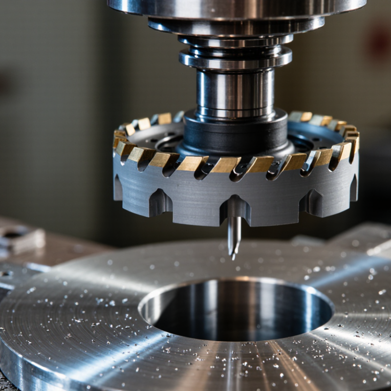
A TCT annular cutter is a hole-making tool with tungsten carbide tips fixed around its cutting edge. TCT means tungsten carbide tipped. Unlike a twist drill, it removes material only around the hole’s circumference. This annular, or ring-shaped, design leaves a solid metal core. The cutter can therefore produce large holes with less material removal and lower resistance.
During operation, the carbide tips cut narrow grooves as the tool rotates. The central core stays intact until the cutter breaks through the workpiece. Ejector pins or built-in space then help release the core. In workshop use, this design often gives clean holes in steel plates, structural sections, and other tough metals. Feed pressure, cutting speed, and cooling must match the material. Excessive force can chip the tips, even when the cutter feels stable. That detail is easy to underestimate.
Tips: Secure the workpiece before cutting. Use suitable cutting fluid and steady pressure. Do not force a dull cutter. Inspect each carbide tip for cracks or missing edges. A short trial hole can reveal vibration, poor alignment, or an unsuitable speed. Results may vary with plate hardness and machine rigidity, so practical adjustment still matters.
A TCT annular cutter removes metal through a controlled 12–150 mm ring. TCT means tungsten carbide-tipped. Its teeth cut the outer circumference, not the entire hole area. The center remains untouched until the inner slug breaks free.
A pilot pin guides the cutter and marks the hole center. As the tool rotates, each carbide tip removes a small chip from the ring. Coolant carries heat and chips away from the cutting zone. This design can reduce cutting resistance compared with full-area drilling. The difference becomes obvious on thick steel plates.
The 12–150 mm range covers small mounting holes and large structural openings. Hole size, plate thickness, spindle speed, feed rate, and carbide geometry must match. The World Steel Association reported 1.89 billion tonnes of crude steel production in 2023, showing the scale of material commonly processed. That figure does not prove every application needs annular cutting. It only explains the demand for efficient steel-hole production. The U.S. Department of Energy’s Manufacturing Energy and Carbon Footprints report also identifies metal manufacturing as a major industrial energy user. Less removed material can mean less cutting effort, but this is not automatic. Poor lubrication still causes chipped tips, rough walls, and premature failure. Clearance matters. So does operator judgment.
A TCT annular cutter removes material through a ring of carbide-tipped teeth, leaving a solid core instead of cutting the entire hole area. The chart shows the calculated material removed over a 10 mm cutting depth, assuming a 6 mm pilot opening.
Annular cutting is especially efficient as diameter increases because the cutter removes only the annular wall. Values are based on the geometric area of the ring: π/4 × (outer diameter² − inner diameter²).
A TCT annular cutter removes a ring of metal, not the entire hole core. Its pilot pin locates the cutter against the workpiece and keeps the tool centered. As the teeth enter, the pin retracts and helps guide the slug through the cutter body. This reduces friction and prevents the familiar wandering seen with twist drills.
The carbide teeth perform the real cutting. Their sharp edges shear a narrow annulus, while the steel body carries torque and resists bending. The U.S. Geological Survey reported about 81,000 metric tons of global tungsten mine production in 2023. That matters because tungsten carbide supports the teeth’s hardness and heat resistance. Still, hard does not mean unbreakable. Excessive feed, poor coolant flow, or a tilted machine can chip the tooth corners quickly.
Cutting depth must match the cutter’s rated capacity, with some working clearance for the pilot pin and ejected slug. A 50 mm cutter should not be forced through a 50 mm plate without checking the tool maker’s limits. In practice, I have seen operators blame the cutter when the real problem was a loose magnetic base. That assumption deserves more care.
Tips: Keep the pilot pin sharp and correctly sized. Use steady pressure, not impact loading. Check chip shape during cutting; long, blue chips suggest excessive heat. Stop if the slug binds.
| Cutter Feature | Typical Geometry or Specification | How It Works | Practical Effect |
|---|---|---|---|
| Cutting principle | Annular, or ring-shaped, cutting path | The teeth remove material around the outside of the hole instead of machining the complete hole area. | Requires less power and produces a solid cylindrical slug rather than a large volume of chips. |
| Carbide teeth | Tungsten-carbide-tipped cutting edges, commonly brazed or mechanically secured to a steel body | Each tooth takes a controlled portion of the cutting load as the annular body rotates. | Provides high wear resistance and supports faster cutting in structural steel, stainless steel, and other metals when the correct speed and feed are used. |
| Tooth arrangement | Multiple teeth distributed around the annular rim; tooth count varies with diameter and design | The staggered cutting action divides the chip load and helps prevent one edge from carrying the entire load. | Can improve cutting smoothness, tool life, and chip evacuation compared with a single-point cutting edge. |
| Pilot pin | Spring-loaded or sliding pin positioned concentrically inside the cutter | Centers the cutter, guides the initial engagement, and retracts as the teeth enter the workpiece. | Improves hole positioning and helps eject the finished slug after the cut. |
| Pilot-pin function during breakthrough | Pin moves through the workpiece before the cutting teeth fully break through | The pin helps maintain alignment and provides a controlled indication that the slug is close to release. | Reduces wandering and helps limit sudden tool movement at breakthrough. |
| Available cutting depths | Common nominal depths include approximately 25 mm, 35 mm, 55 mm, 75 mm, and 100 mm | The cutting depth is the maximum material thickness the tooth section is designed to pass through in one operation. | The selected depth must exceed the workpiece thickness while allowing adequate chip space and arbor clearance. |
| Cutter diameter | Common metal-cutting sizes are approximately 12–100 mm, with larger sizes available for specialized equipment | The diameter determines the finished hole size and influences the required spindle torque. | Larger diameters generally require lower rotational speed and greater machine capacity. |
| Shank and arbor interface | Common interfaces include Weldon-style flats and other machine-specific arbor systems | The arbor transfers rotary torque and axial feed from the magnetic drill, drill press, or compatible machine to the cutter. | Correct fit is essential for concentricity, torque transmission, and safe operation. |
| Cutting action | Combination of radial cutting and axial feed | The spindle rotates the cutter while the machine feeds it steadily into the material. | Steady feed helps produce consistent chips and reduces tooth rubbing or edge chipping. |
| Chip gullets | Flutes and spaces between teeth sized for chip transport | Gullets carry chips away from the cutting zone and provide space for cutting fluid to reach the teeth. | Blocked gullets increase heat, vibration, and the risk of premature tooth failure. |
| Coolant or cutting fluid | External or internal delivery, depending on the arbor and cutter system | Fluid cools the carbide teeth, reduces friction, and assists chip removal. | Improves edge life and surface finish; dry cutting should only be used when permitted by the tool and workpiece requirements. |
| Typical work materials | Carbon steel, stainless steel, cast iron, and selected non-ferrous metals | Carbide geometry and cutting parameters are matched to the hardness, toughness, and thermal behavior of the material. | Material-specific speed, feed, lubrication, and tooth geometry are required for reliable results. |
| Recommended machine setup | Rigid magnetic drill, drill press, or other machine with suitable arbor capacity | The machine supplies controlled rotation, axial feed, and sufficient torque without excessive runout. | A rigid setup reduces vibration, improves hole accuracy, and protects the carbide teeth. |
| Key operating limitation | Cutting depth and parameter limits depend on cutter construction and material | Exceeding the rated depth or forcing the feed can overload the teeth and arbor. | Always verify the cutter specification, machine capacity, workpiece thickness, spindle speed, and feed before cutting. |
A TCT annular cutter uses carbide-tipped teeth to remove a ring of metal. The center becomes a solid slug, not chips. Its pilot pin locates the hole and helps eject the slug after cutting. In shop practice, cutting speed commonly ranges from 50 to 150 m/min. The correct value depends on cutter diameter, steel grade, machine rigidity, and coolant.
Clamp the workpiece firmly and check that the arbor runs smoothly. Fit the pilot pin, then align the cutter with the marked center. Select spindle speed with this formula: rpm = 1,000 × cutting speed ÷ π × cutter diameter. For a 30 mm cutter at 100 m/min, the result is about 1,060 rpm. Start at a controlled feed. Let the carbide teeth cut continuously, but do not force them into the plate.
Apply suitable cutting fluid before engagement and keep the cutter lubricated. Watch for vibration, blue chips, or a sudden change in motor sound. These signs often mean excessive speed, poor clamping, or insufficient feed. Breakthrough needs care; reduce pressure slightly as the slug separates. The first hole is not always perfect. I still inspect the slug, hole wall, and tooth edges before increasing speed. Thin material may require a different cutter or slower settings, despite the nominal 50–150 m/min range.
A TCT annular cutter uses tungsten carbide tips to cut a circular ring through metal. Unlike a twist drill, it removes only the material around the hole. A pilot pin guides the cutter and helps eject the central slug. The core remains mostly intact. This design reduces cutting resistance and produces fewer chips.
Twist drills remove the entire hole volume, so they consume more material and often demand higher feed pressure. An annular cutter can create the same opening with less metal removal. This may reduce machine load, heat, and cutting time. The difference becomes clear on thick steel plates. However, performance depends on machine rigidity, cutting speed, lubrication, and operator control. A loose setup can still produce rough holes.
TCT annular cutters commonly offer cutting depths from 35 to 80 mm. A 35 mm cutter suits thinner plates and compact work areas. An 80 mm option reaches deeper sections without repeated drilling. Always confirm the actual cutting depth, shank type, and pilot-pin length before use. Carbide tips are hard but not indestructible. Sudden contact, poor alignment, or excessive feed can chip them. Real cuts vary. I have found that a slower, steady feed often gives better results than forcing the tool. Inspect the hole edge and removed slug after drilling. Those details reveal whether the setup worked properly.
It is a hole-making tool with tungsten carbide tips around its cutting edge. TCT means tungsten carbide tipped. It cuts a ring, not the whole hole. The center remains as a solid metal slug.
A twist drill removes material across the entire hole. An annular cutter removes only the outer ring. This usually lowers cutting resistance and produces less waste. The difference becomes clear in thick steel plate.
The pilot pin centers the cutter against the workpiece. It guides the tool during entry. It also helps release the metal slug after breakthrough. Keep it sharp and correctly sized.
It commonly cuts steel plates, structural sections, and other tough metals. Performance depends on hardness, thickness, and machine rigidity. Harder material may require slower settings. Results can vary.
Typical cutting speed ranges from 50 to 150 m/min. The correct value depends on diameter, steel grade, coolant, and machine stability. Do not treat this range as a fixed rule.
Use this formula: rpm = 1,000 × cutting speed ÷ π × cutter diameter. For a 30 mm cutter at 100 m/min, the speed is about 1,060 rpm. Check the machine setting carefully.
Watch for vibration, blue chips, unusual motor sounds, or a binding slug. These signs may indicate excessive speed, weak clamping, or poor lubrication. Stop and inspect the setup.
Secure the workpiece firmly. Apply suitable cutting fluid before engagement. Use steady pressure instead of impact loading. Inspect each tooth for cracks or missing edges. Do not force a dull cutter.
Reduce pressure slightly as the slug separates. A sudden breakthrough can damage teeth or disturb alignment. Inspect the slug, hole wall, and cutter after the first hole. The first result may not be perfect.
A TCT Annular Cutter is a core-cutting tool fitted with tungsten carbide tips that remove material around the outside of a hole rather than grinding away the entire center. Its ring-shaped cutting action can produce holes approximately 12–150 mm in diameter while leaving a solid core that can be ejected after cutting. This design reduces the volume of material removed and can improve cutting efficiency compared with conventional twist drills.
The cutter’s pilot pin helps position the tool and guides it into the workpiece, while the carbide teeth perform the main cutting action. Depending on the tool and material, cutting depths commonly range from 35–80 mm. During operation, the cutter is aligned securely, supplied with suitable cooling or lubrication, and run at typical cutting speeds of about 50–150 m/min. Correct speed, feed pressure, and chip clearance help maintain clean holes, extend tool life, and support stable performance.